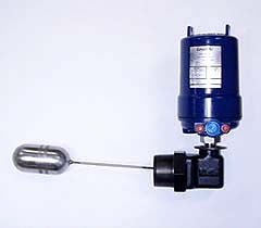
LevelAc's SL-500 Series of level switches are designed for mounting through the side of a tank at the point where the liquid level is to be controlled. It is equipped with an elliptical float to facilitate installation through small openings. By changing the float road length, the operating differential may be extended to 15" as compared to 3½" for top-mounted, float-actuated LevelAc's.
NOTE - Explosion-proof and Vapor-proof housings are U/L and CSA Approved as float-operated motor control unit for use in hazardous locations.
Because of the lever system required in the elbow construction of SL-500, some aspects of its operation differ from top-mounted instruments. At low liquid level conditions, the magnetic field of a single switch station and normal switching action occurs from a downward travel of the armature into the switch station's magnetic field in response to rising liquid level. For two-station instruments, the armature works between the stations, moving upward into the field of the upper station on falling level and downward into the field of the lower station on rising level.
Care in wiring must be used to ensure proper operation.
Mercury Switching Station - A glass capsule containing the mercury and switch contacts is mounted on a pivoted arm. A magnetic armature moves up and down inside a non-magnetic sealing tube following movement of the float caused by changing liquid level in the float chamber. As the armature enters the field of the Alnico V magnet mounted on the opposite end of the pivoted arm, magnetic attraction causes the magnet to approach the sealing tube and tilt the mercury capsule to make or break an electrical circuit.
Snap Switching Stations: - An Alnico 8 magnet surrounds the sealing tube and concentrates powerful magnetic force in a small space. Movement of the armature into the magnetic field shunts attraction away from the external pole pieces which allows the pivoted actuator plate to "snap" the SPDT switch making the circuit "COM" to "NC" and breaking "COM" to "NO".
See following chart.
When specified on order, the switching differential between the limits shown in the "Liquid Differential" column can be furnished. If not specified, the differential shown in "Maximum Setting" column will be furnished
NOTE - The factory set differentials for two switching stations are based on maximum separation of switching stations and as such the values tabulated correspond to "High-Low" operation.
| DIM. L In. | At Min**Setting | At Max**Setting |
|---|---|---|
| 6 | 2" Max | 5" Min |
| 12 | 2 1/2 " Max | 8 1/2" Min |
| 18 | 3" Max | 12" Min |
| 27 | 4 1/2" Max | 14 1/2" Min |
| DIM. L In. | Series at Min** Setting |
Series at Max*** Setting |
High-Low at Min*** Setting |
High-Low at Max *** Setting |
|---|---|---|---|---|
| 6 | 1 1/2" Max | 3" Min | 3" Max | 4 1/2" Min |
| 12 | 2" Max | 5" Min | 5" Max | 8" Min |
| 18 | 2 1/2" Max | 6" Min | 7" Max | 11 1/2 " Min |
| 27 | 3" Max | 9" Min | 9" Max | 15" Min |
* With switch stations set at minimum spacing, actual differential may be slightly less than vaIues tabulated. With switch stations set at maximum spacing, actuaI differential may be sIightly more than minimum value tabulated. Unless specified on order, switching stations will be set at maximum spacing.
** Differential adjusting nut spacing.
*** Switch station spacing.
| Dim. L | Std. Pipe Size, NPT | Max. Ext. Lgt. | |||||||
|---|---|---|---|---|---|---|---|---|---|
| - | 2 1/2 | 3 | 3 1/2 | 4 | 5 | 6 | 8 | 10 | - |
| 6 | No Extention allowable | " " | " " | " " | " " | " " | " " | No Extention allowable | - |
| 12 | 1 | 2 | 3 | 3 | 5 | 6 | 6 | 6 | 6 |
| 18 | 1 | 2 | 3 | 4 | 5 | 7 | 10 | 12 | 12 |
| 27 | 3 | 4 | 6 | 6 | 8 | 10 | 14 | 17 | 17 |